4 pin relay diagram ground trigger 1 8K 169K views 3 years ago Automotive Wiring How To s In this video I explain why it is necessary to use a relay in a circuit I then demonstrate how to wire a 5
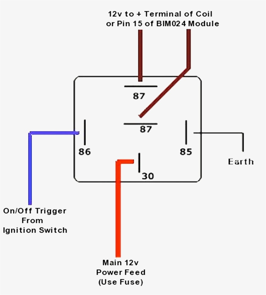
Wiring a 4 Pin Relay Let s walk through wiring a basic 4 pin relay for switching power to a light or other load Step by Step Wiring Instructions Determine load By following the wiring diagram you can easily connect the 4 prong relay to the appropriate wires and terminals This allows the relay to control the flow of electrical
4 pin relay diagram ground trigger

4 pin relay diagram ground trigger
https://i1.wp.com/www.automationcontrols.com.pk/wp-content/uploads/2019/10/1-4.jpg?strip=all

4 Pin Relay Wiring Diagram Starter Circuit Diagram
https://i2.wp.com/img.joomcdn.net/7edea646da59a17bdb8ee9a942cd3e7987cc16da_1024_1024.jpeg?strip=all

5 Pin Wiring Diagram
https://i.pinimg.com/originals/5a/d8/7e/5ad87e388d3cbce09db266d41ddf5005.jpg
Apr 30 2015 at 13 58 You are connecting the ground when you turn on the relay so yes at that point your Arduino output is at ground However when it is DISABLED you still have 12V on the relay which means 12V AllWiringDiagrams 432 subscribers Subscribed 13 966 views 4 months ago Pin Learn how to wire a standard 4 pin automotive or powersports relay in this quick
21 Jun 2023 A Guide to Wiring 4 Pin and 5 Pin Relays Detailed Diagrams Wiring relays can be tricky but not anymore Our detailed guide with diagrams will help you The Omron 4 pin relay diagram illustrates the internal structure and connections of the relay By understanding this diagram you can easily determine the pin configurations
More picture related to 4 pin relay diagram ground trigger

Bosch Style Relay Wiring
https://i.pinimg.com/originals/30/8a/4a/308a4a699dcbf07ab6a4808e10c0c120.jpg

Automotive Relay Wiring Diagram Ford
https://2020cadillac.com/wp-content/uploads/2019/02/ford-wiring-5-pin-relays-wiring-diagram-detailed-5-prong-relay-wiring-diagram.jpg

Wiring A 12v Relay
https://mgispeedware.com/wp-content/uploads/2019/05/relay-socket-wiring-diagram-4-pin.jpg
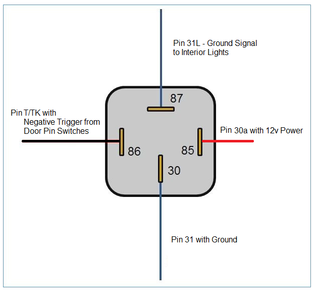
The Dorman 4 pin relay has four pins labeled as 30 87 85 and 86 It is important to understand the function of each pin before proceeding Pin 30 is the power supply input To wire a 4 pin relay start by connecting pin 85 to the positive terminal of the power source that will trigger the relay Then connect pin 86 to the ground or negative terminal of the
How is a 4 Pin Relay Wired Using a relay is an effective and efficient way of controlling electrical circuits on low voltage without having to use direct current A four This video will explain details of how to wire a relay switch for off road lights compressors or any other added accessory We re using a four pin relay couldn t be

Negative Trigger Relay Wiring Coloric
https://cimg2.ibsrv.net/gimg/rennlist.com-vbulletin/626x600/switched_ground_relay_e85802a59eecd3bf36896bb295efb22a1a905679.png

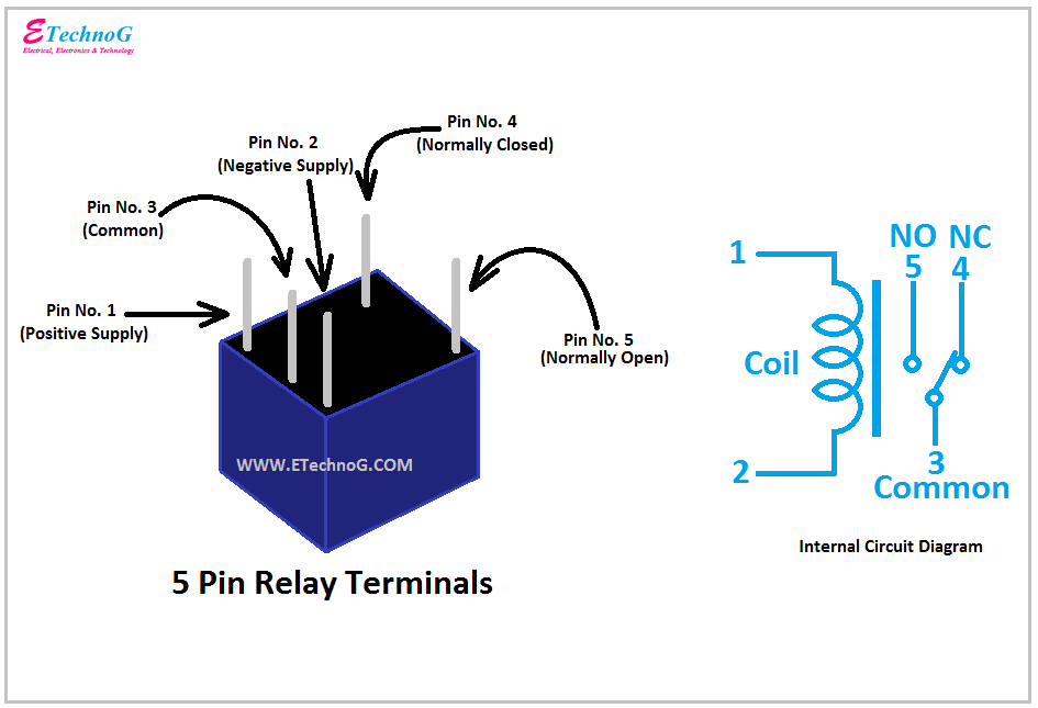
5 Pin Relay Wiring Diagram Ground
https://1.bp.blogspot.com/-LWofair4FMo/YQFwXxaL5mI/AAAAAAAABVI/Zu0ZXHUJl9Av4P89VH10vGms_vUIavOVACLcBGAsYHQ/s945/5%2Bpin%2BRelay%2Bterminals.png
4 pin relay diagram ground trigger - The Omron 4 pin relay diagram illustrates the internal structure and connections of the relay By understanding this diagram you can easily determine the pin configurations